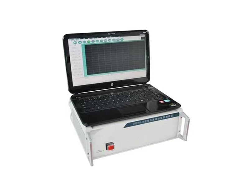
Portable Transformer Sweep Frequency Response Analyzer Winding Deformation Tester
If you are interested in our products or need technical supports and service,please contact us as bellowing:
- Details
During testing, transformers may experience inter-turn or inter-phase short circuits, or suffer collisions during transportation, causing relative displacement of the windings. Furthermore, electromagnetic forces during short circuits and fault conditions during operation can cause winding deformation. These events alter the distributed parameters of the transformer windings, consequently affecting and changing the transformer's original frequency domain characteristics, such as amplitude changes and shifts in resonant frequencies in the frequency response. The transformer winding tester, developed based on response analysis methods, is a novel non-destructive testing device for internal faults in transformers. It is suitable for detecting internal structural faults in power transformers ranging from 63kV to 500kV.
1. The data acquisition and control system utilizes a high-speed, highly integrated microprocessor.
2. Communication between the laptop and the instrument is via a USB interface.
3. The industrial control computer and measuring instrument are integrated into a single unit, eliminating the need for a separate mobile computer at the measurement site.
4. The hardware core adopts dedicated high-speed digital sweep frequency technology (from the USA), which allows for accurate diagnosis of winding faults such as twisting, bulging, displacement, tilting, inter-turn short circuits, and phase-to-phase short circuits through testing.
5. High-speed dual-channel 16-bit A/D sampling (the waveform curve shows clear changes when the tap changer is adjusted during field testing).
6. Signal output amplitude is software adjustable, with a maximum peak value of ±10V.
7. The computer generates an electronic document (Word) of the test results.
8. The instrument features both linear sweep frequency measurement and segmented sweep frequency measurement functions, compatible with the two current mainstream measurement modes in China.
| Transformer Winding Deformation Tester | ||
| Parameter | GDRB-B (GDRB-C) | GDRB-F (Impedance Two-in-One) |
| Linear Sweep Distribution | ||
| Sweep Frequency Range | 1kHz - 2MHz | 1kHz - 10MHz |
| Sweep Points | 2000 | 4000 |
| Resolution | 1kHz | 0.25kHz / 0.5kHz / 1kHz |
| Sweep Measurement Range | ||
| Measurement Range | 0.5kHz - 1MHz | 0.5kHz - 1MHz |
| Sweep Points | 2000 | 2000 |
| Resolution | 0.02kHz - 1kHz | 0.02kHz - 1kHz |
| In-phase Test Repeatability | 99.50% | 99.90% |
| Amplitude Measurement Range | -100dB ~ +20dB | -120dB ~ +20dB |
| Signal Input Impedance | 1MΩ | 1MΩ |
| Signal Output Impedance | 50Ω | 50Ω |
| Amplitude Measurement Accuracy | 1dB | 1dB |
| Sweep Frequency Accuracy | < 0.01% | < 0.01% |
| Instrument Dimensions | 300Ω340Ω120 (mm) | 300Ω340Ω120 (mm) |